Voiding the Warranty - Merkury Smart Plug
Table of Contents
The Cause - Why do this?
Studying infosec and IoT device security has given me a desire to create my own gadgets and practice some of what I’ve learned. What better way than destroying some cheap off-the-shelf devices found at a local store and share my process with others?
Some may ask, “why would I do that when there are options such as Arduino, ESP32, and ESP8266 that are available?”
Availability
Since I am located out in a rather rural area, if I want an Arduino board or similar, I have to order it online. After I pay for the device and additional shipping, I patiently wait for my device to arrive in the hopes that the order is correct, and the device is functional. By sourcing inexpensive devices locally, I can cut cost, avoid shipping, and skip waiting and crossing my fingers. Also, these devices are usually sold in packs of 2-4 at a cost comparable or cheaper than the cost of a single Arduino without shipping added.Peripherals
Although these devices usually function as simple hardware such as a light bulb or power plug, there is much more to them. Smart devices contain a processor as well as WiFi and Bluetooth chipsets to provide internet connectivity to enable remote control and timer programming capability. Included in the device I will be modifying is a WiFi adapter (capable of acting as access point and station simultaneously), Bluetooth capability, GPIO, and I2C!
To add such functionality to some Arduino, ESP32, or ESP8266 would require additional parts, which would in turn incur additional cost per project.Versatility
Smart devices have an operating system of some form such as Linux or an RTOS. This means they have a program that instructs the device what to do, and that program is usually modifiable if it can be accessed and written to. If I can figure out how to flash my own firmware to these devices, I can write my own code, utilize additional libraries, and perform functions with the device not intended by the manufacturer.
I don’t see a reason not to at least give it a try.
So, without further ado, let’s break something.
The Victim - Choosing the device
The first device I chose to violate is a Merkury Smart Plug. These are currently sold near me for around $13 a pair (yay for spare).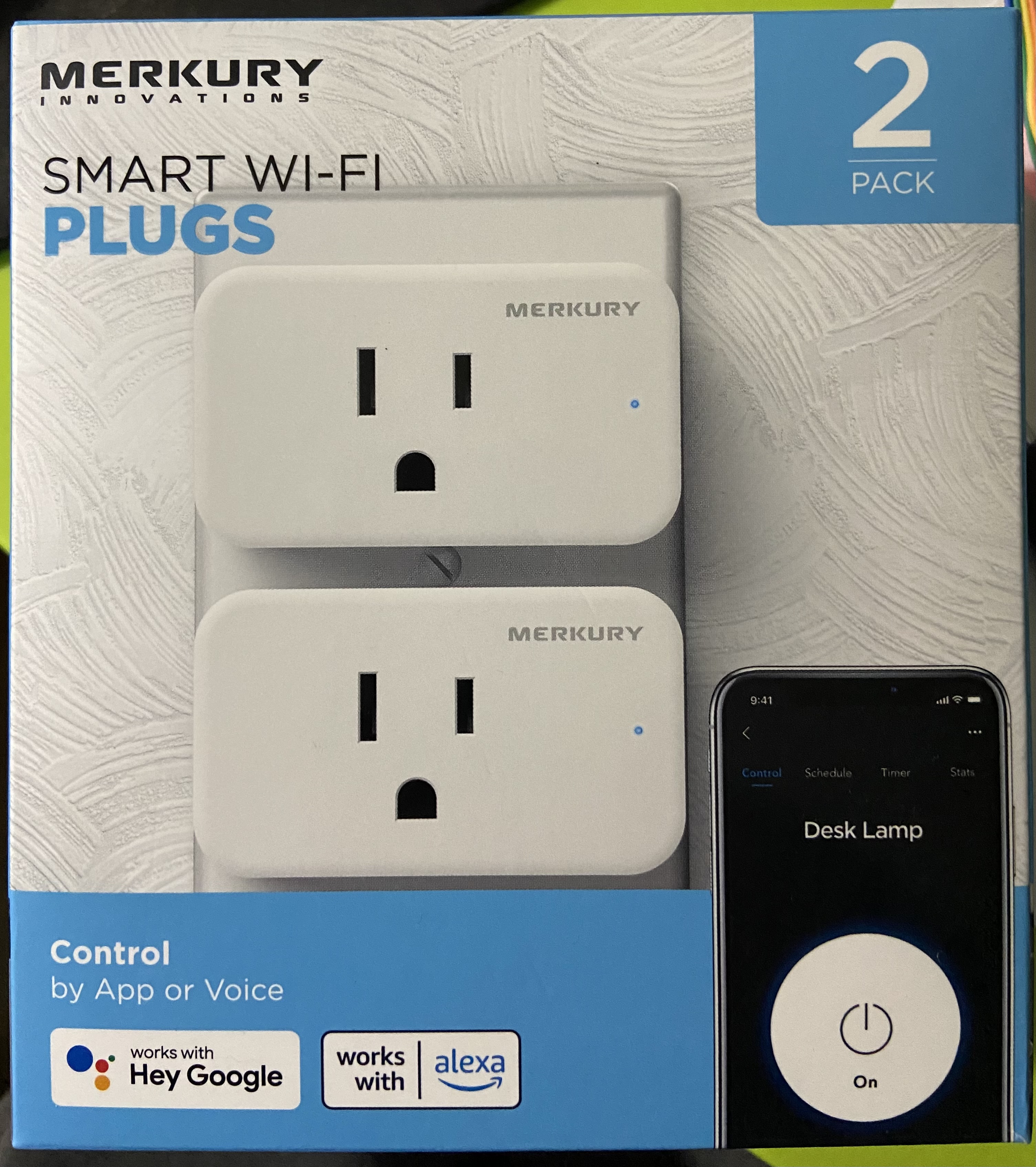
| Plug Front | Plug Back |
|---|---|
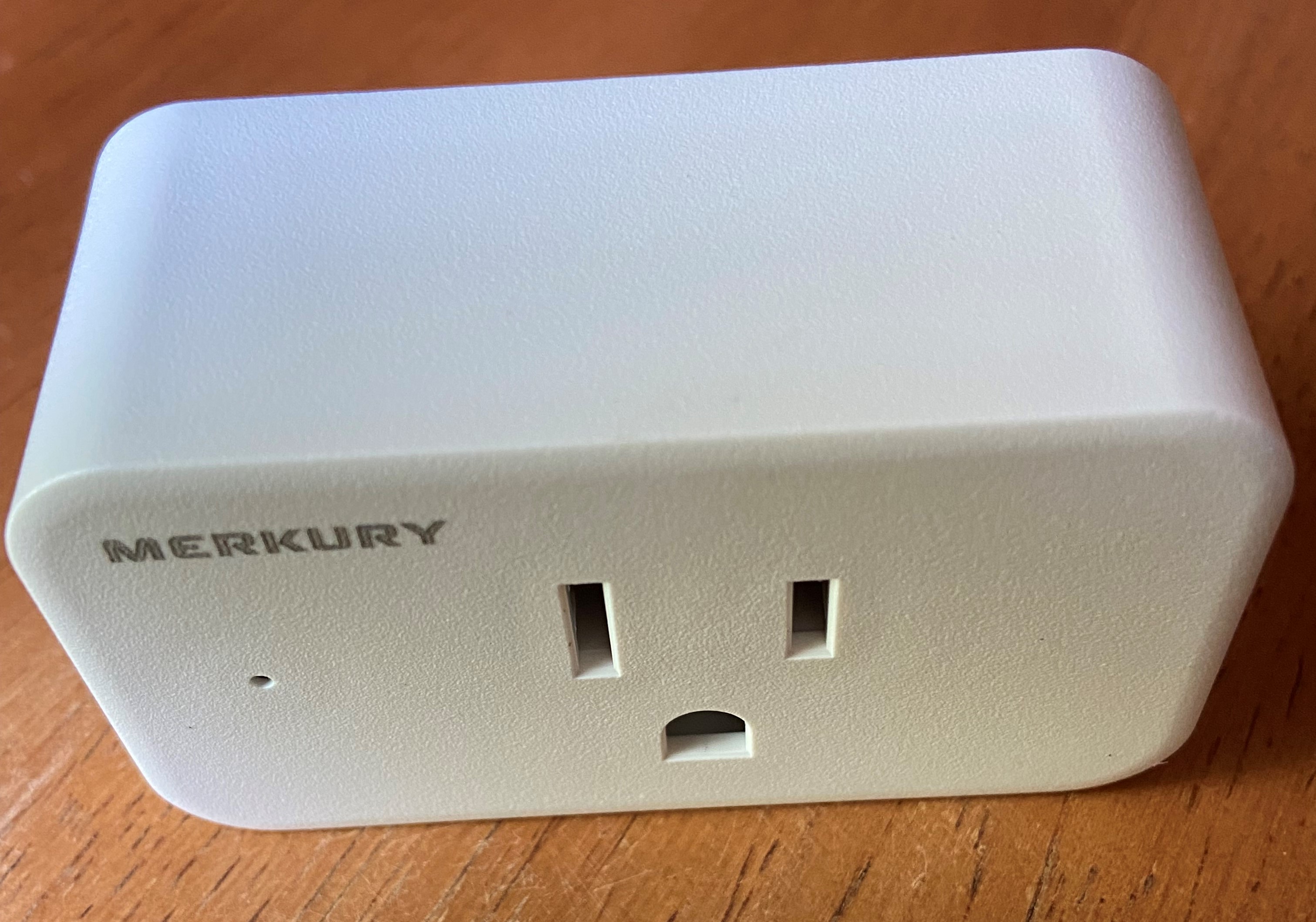 | 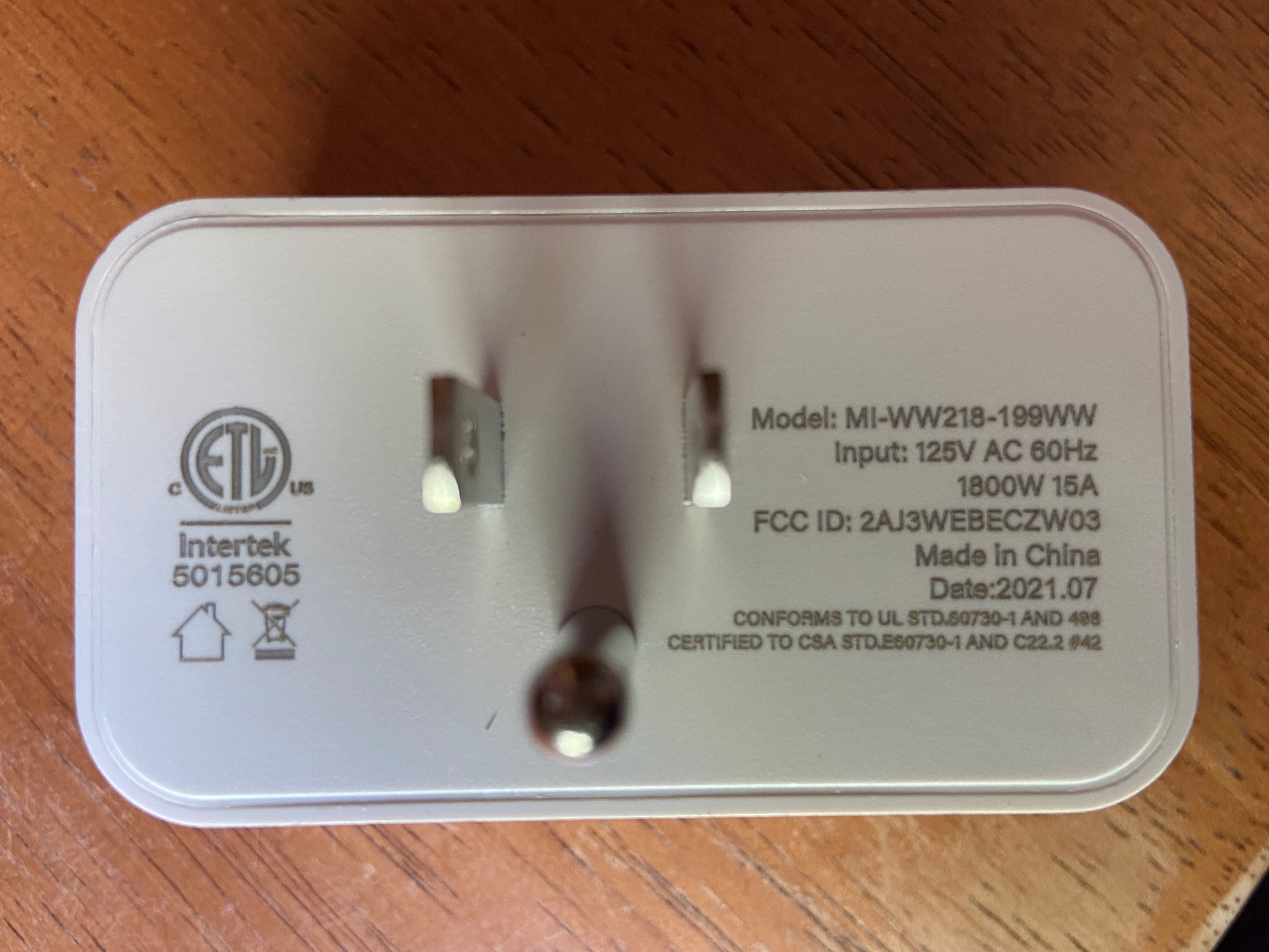 |
If we search for the FCCID 2AJ3WEBECZW03 from the back of the device at fcc.gov we will find disassembled photos showing that the cover is held on by glue around the edge. We can also see the part number for the chipset, but it is hard to make out for certain.
Using two small screwdrivers I was able to pry around the edge until the cover finally popped off. It doesn’t look pretty and new, but function is more important than form here.
| Under The Hood |
|---|
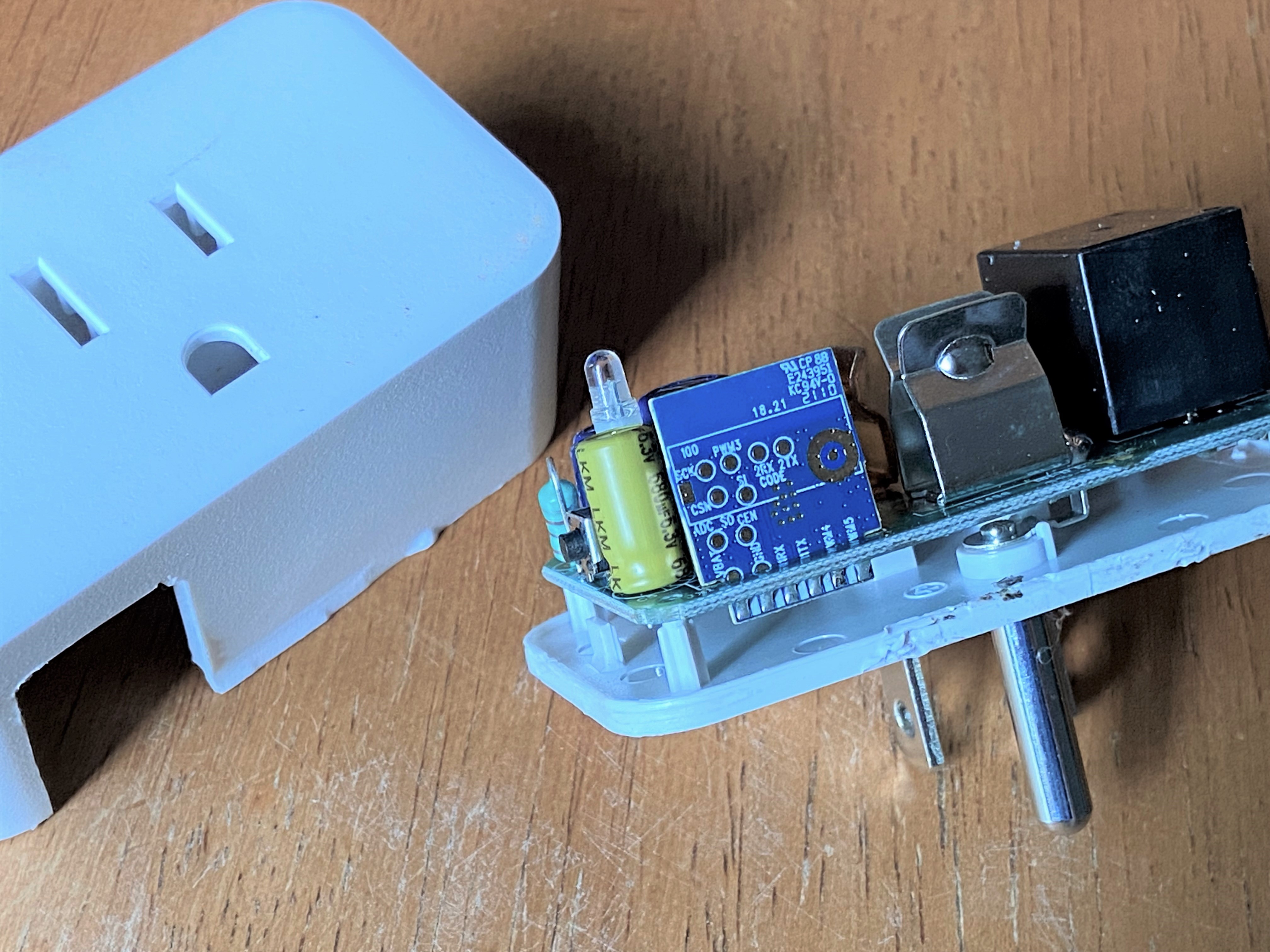 |
We can see on the back of this chipset a few interesting, labeled contacts such as two pair of RX/TX, a VBAT, as well as GND. These are what we
will be utilizing for communication and flashing of the controller.
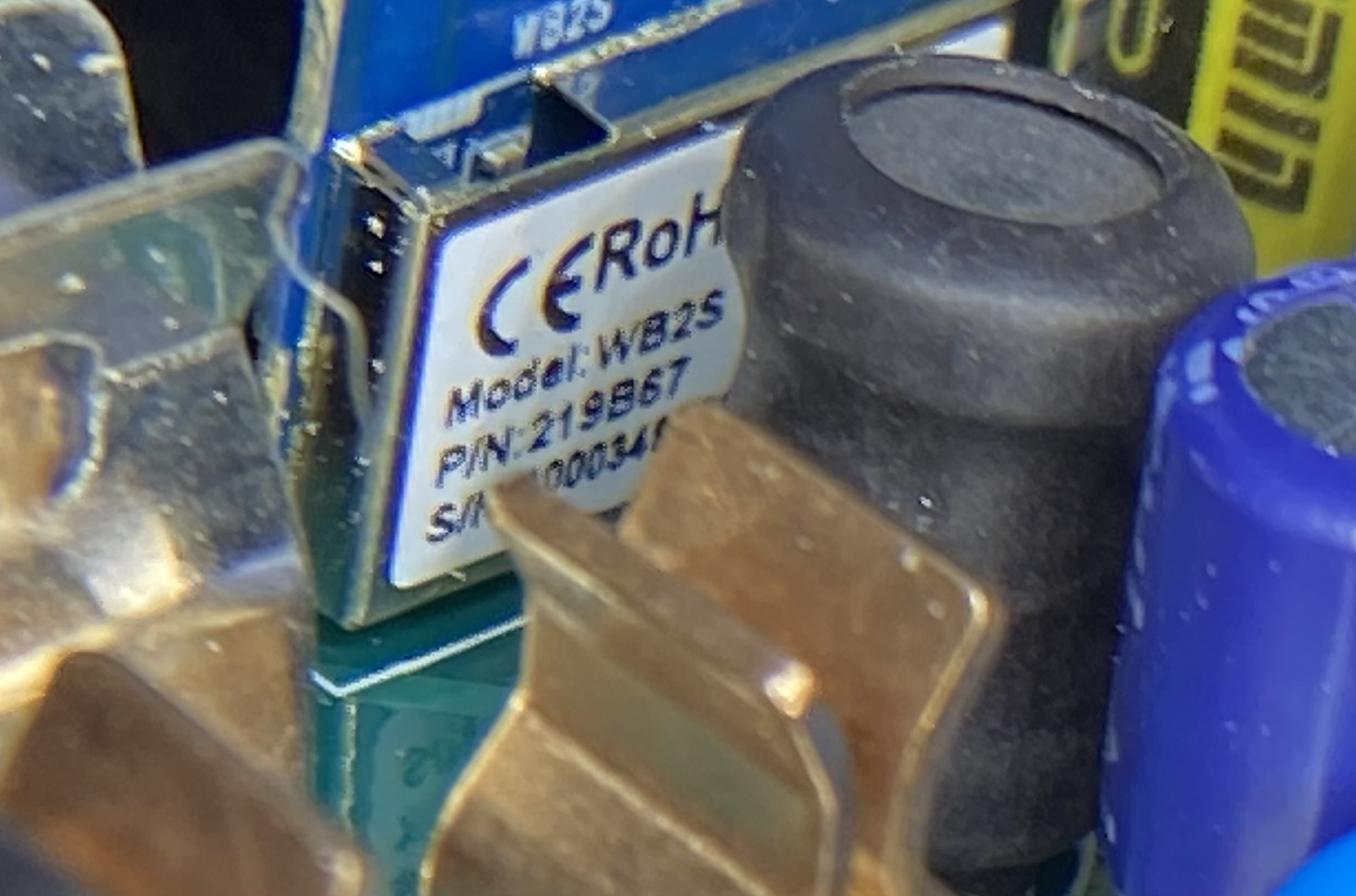
On the front of the chipset we see it is labeled as Model: WB2S. A quick Google search will lead us to the WB2S datasheet provided by Tuya.
A basic rundown of what we have from the datasheet:
Overview
WB2S contains a low-power Arm Cortex-M4 microcontroller unit (MCU), 1T1R WLAN module, 256 KB static random-access memory (SRAM), 2 MB flash memory, and extensive peripherals.
WB2S is an RTOS platform that integrates all function libraries of the Wi-Fi MAC and TCP/IP protocols. You can develop embedded Wi-Fi products as required.
The specific features of the device:
Features
Embedded low-power 32-bit CPU, which can also function as an application processor
Clock rate: 120 MHz
Working voltage: 3.0 V to 3.6 V
Peripherals: nine GPIOs, one universal asynchronous receiver/transmitter (UART), and one analog-to-digital converter (ADC)
Wi-Fi connectivity
802.11b/g/n
Channels 1 to 14 at 2.4 GHz
Support WEP, WPA/WPA2, WPA/WPA2 PSK (AES) ,WPA3 security modes
Up to +16 dBm output power in 802.11b mode
EZ net pairing mode for Android and iOS devices
On-board PCB antenna with a gain of -1.0dBi
Working temperature: -40°C to +85°C
Bluetooth LE
Support Bluetooth (V4.2)
Maximum output power + 6dBm
Onboard PCB antenna
So, it says we have a 120 MHz ARM Cortex-M4 mpu, 256KB RAM, 2MB flash, 2.4Ghz Beken BK7231T wireless chipset, Bluetooth LE, GPIO, UART, and ADC.
The WB2S chipset also happens to run the open source Real-Time Operating System FreeRTOS.
Not a bad deal for about $6.50 total.
Even though the connections are thankfully labeled on the chip, the datasheet also includes a diagram as well. Thanks Tuya!
| WB2S Diagram |
|---|
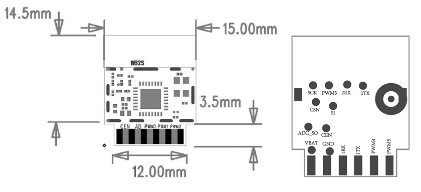 |
Making Connections - Lets get physical
Since this is my first time working with the actual firmware of a device, I took to Google again. Surely someone else has tried to work with these devices, right? After reading through a handful reddit and forum posts asking about the Tuya WB2S, I stumbled onto a forum post at Elektroda:
In the discussion the author describes exactly how he was able to connect the device, read the log output, and flash the device with custom firmware. This sounds to me to be pretty spot-on for what we’re needing.
Tuya has also made the SDK for the chipset open source available here.
While searching for more information on the SDK and BK7231T chipset, I found:
In the write-up, the researchers describe how they went about finding a vulnerability with the Tuya SDK allowing them to jailbreak the device and install custom firmware with OTA update. I was later able to find the video from their presentation at MCH2022 regarding the vulnerability and after their disclosure to Tuya which I think is worth the watch.
This thing is going to be fun!
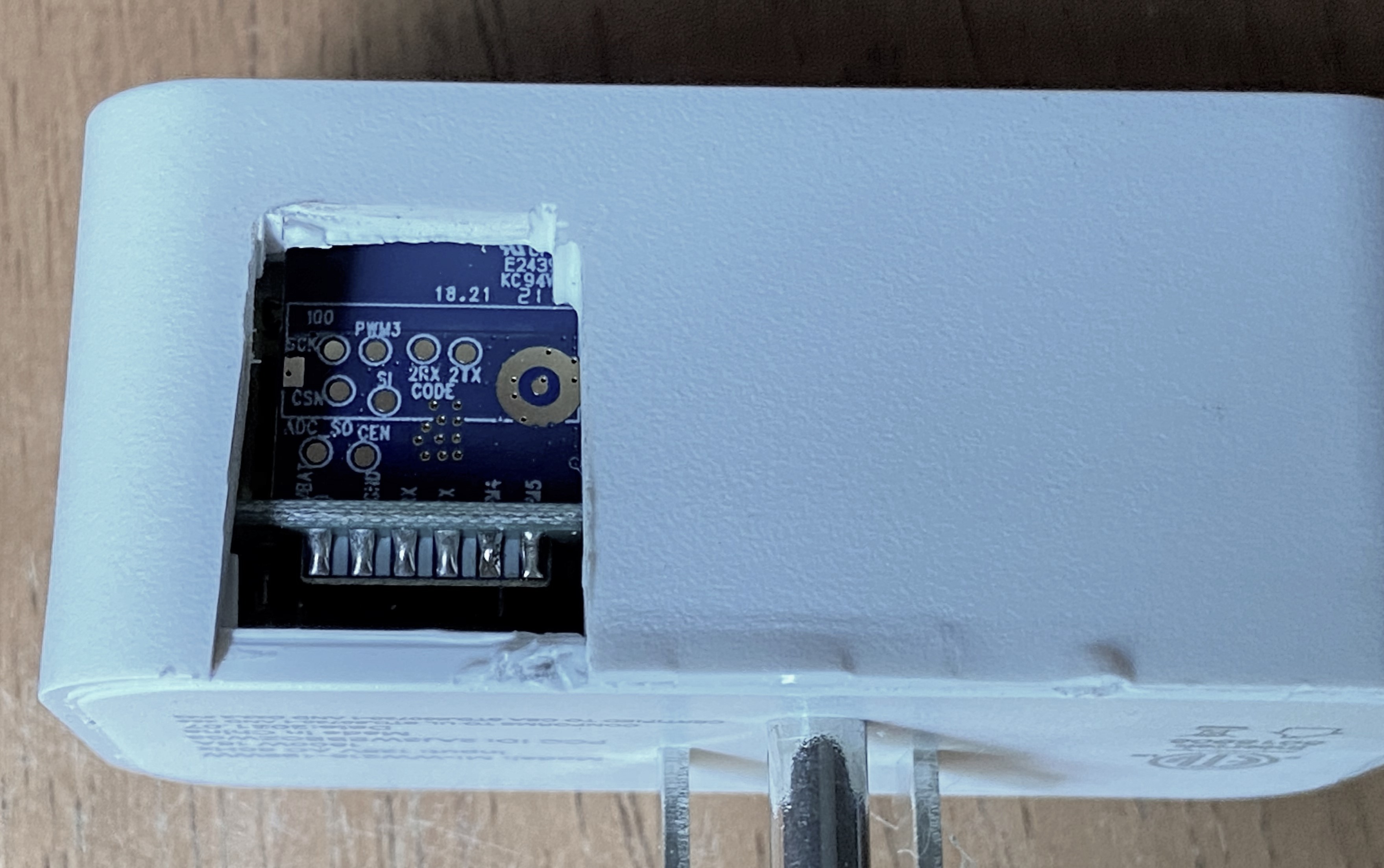
Now, getting back to business, I needed to be able to handle the plug without risk of being shocked by the AC portion of the device while also having access for wiring, so I removed a section of the case for a window. After modifying the case to accommodate wiring, I attached leads to the following connections on the chip:
- VBAT 3.3v power
- GND ground
- RX1/TX1 uart programming
- RX2/TX2 uart logging
- CEN reset
The contact pads are very delicate, so it is recommended to make sure the wiring is extra stable. In the case that one of those pads is pulled even slightly it can separate from the PCB and it may take a bit of finesse to make a new lead on the board. I experienced that with another chipset from a bulb, so I decided to reinforce the connection with hot glue for a little extra insurance.
| Modified Case Installed | Ugly But Works |
|---|---|
 | 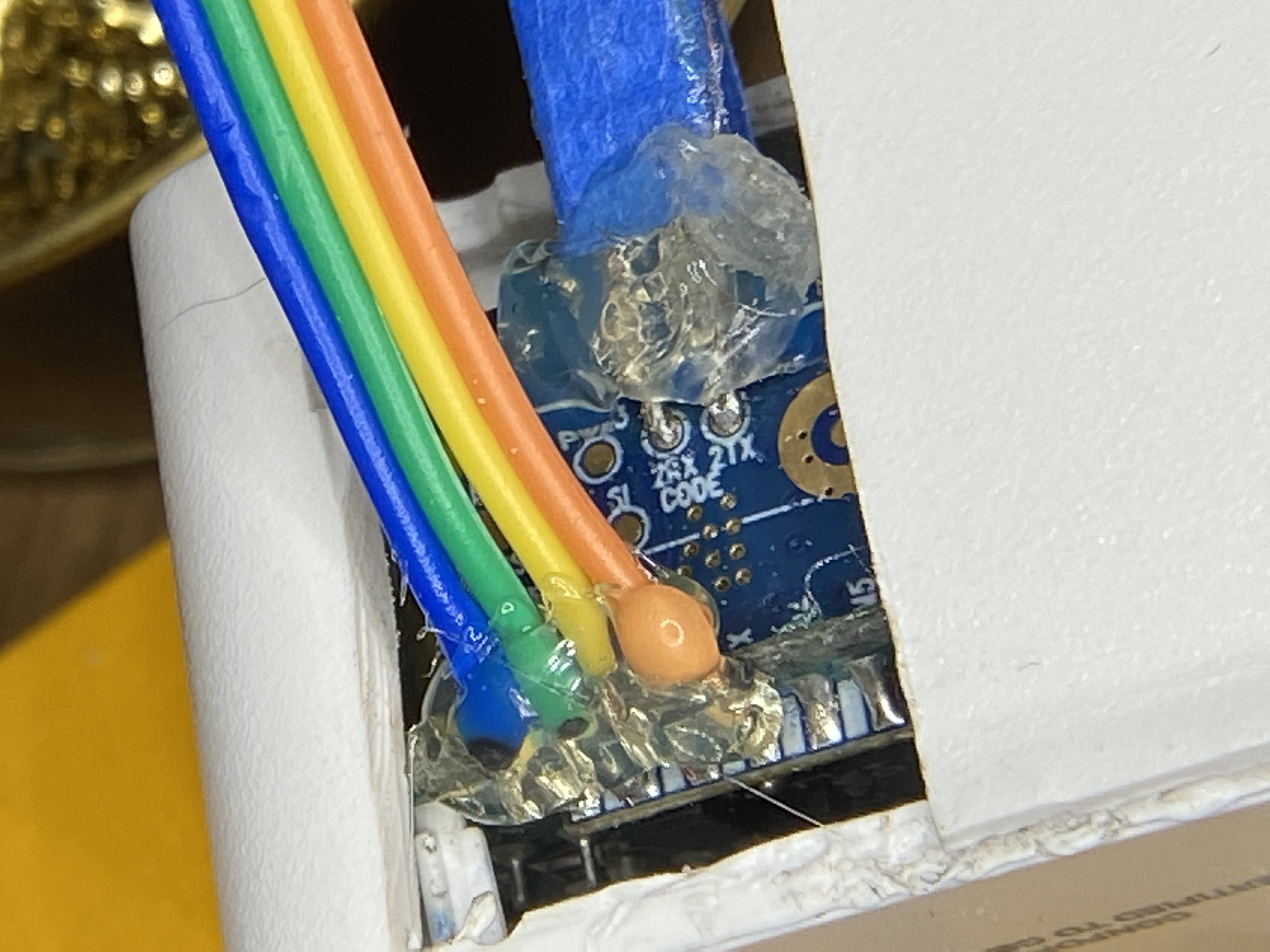 |
I needed a way to connect this device to my computer. What I settled on using were 2xFT232RL FTDI Usb to TTL Serial Adapter that I ordered from Amazon for around $6/each.
Since I only the VCC/GND and RX/TX were needed from each, I was able to use the pins without doing any more soldering. I needed one FTDI adapter for the logging console, and the other to do the programming. The CEN lead will be left open for now as it touched to GND to reset the chip.
| FT232RL Front | FT232RL Back |
|---|---|
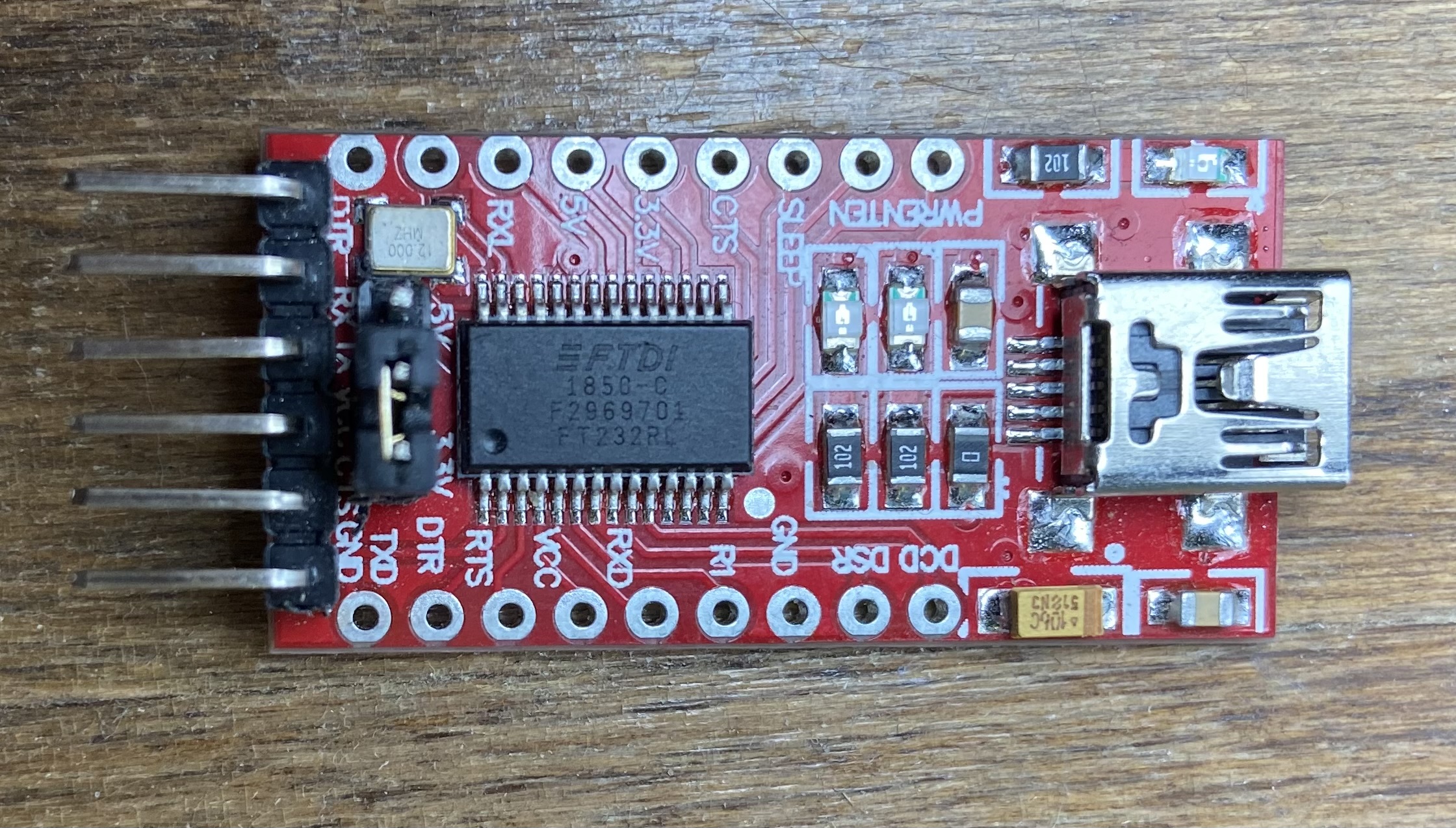 | 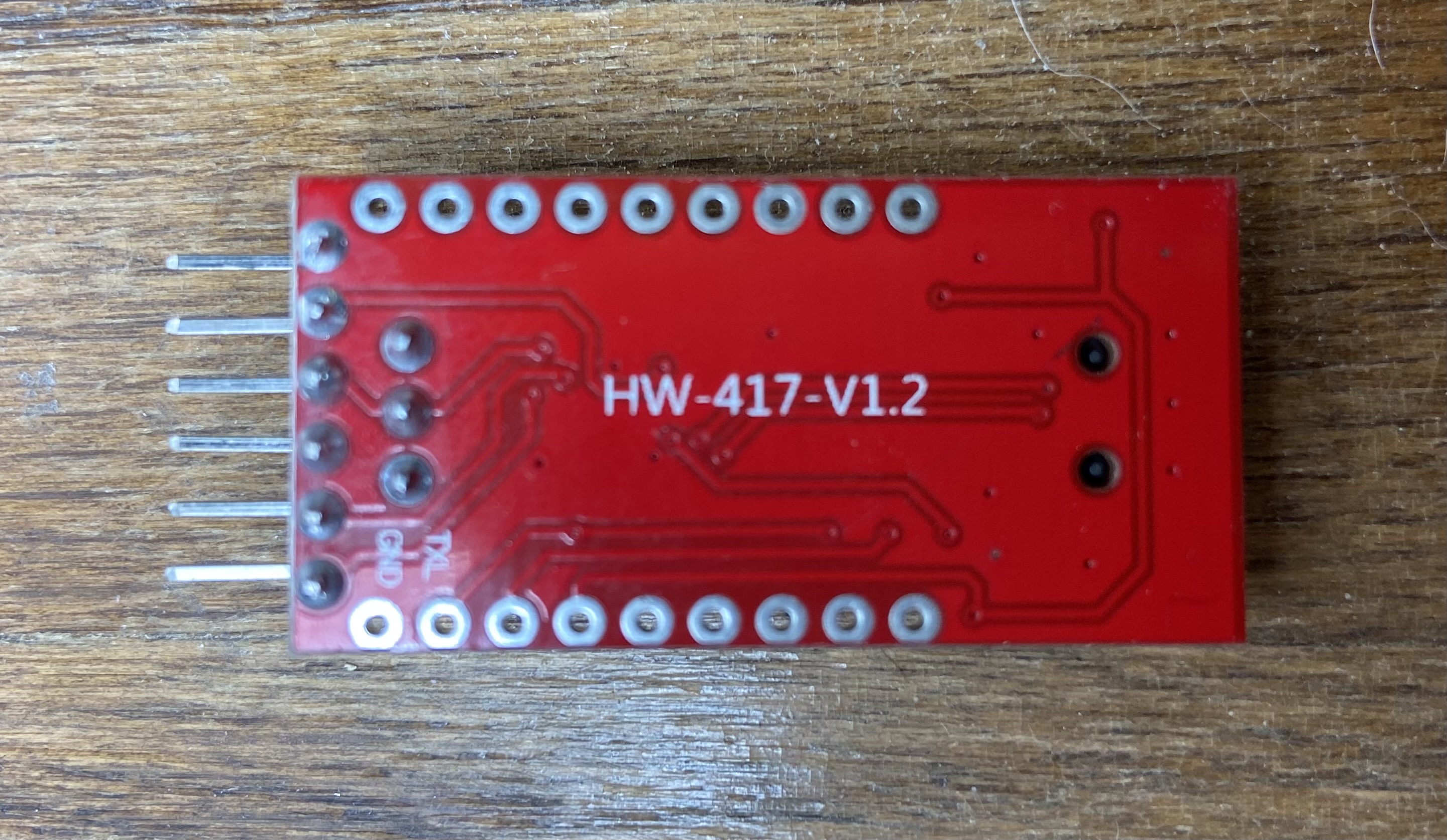 |
| Device to Logging Serial Adapter | Device to Programming Serial Adapter |
|---|---|
| VBAT -> VCC | |
| GND -> GND | |
| 2RX -> TX | 1RX -> TX |
| 2TX -> RX | 1TX -> RX |
I scavenged a reset switch from an old Dell desktop case to make life easier with resets, but it is not required.
| Wired Up | Reset Switch |
|---|---|
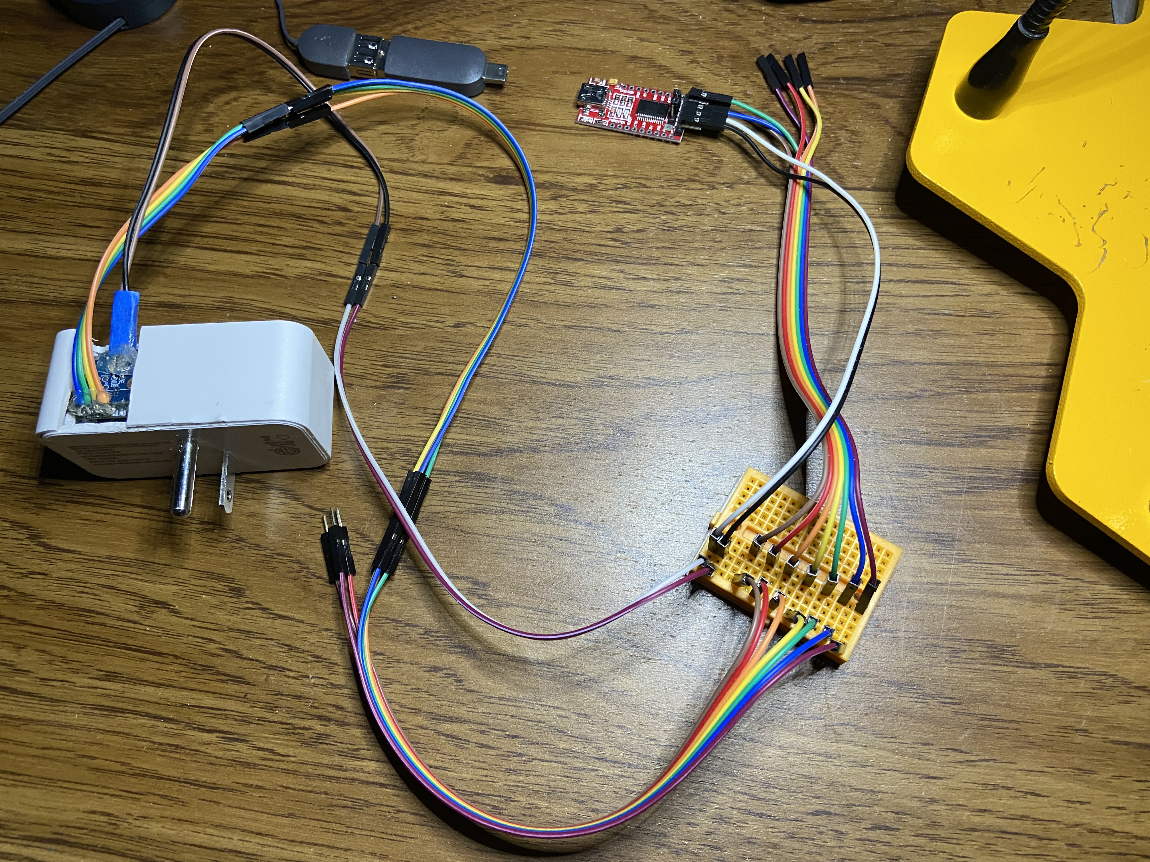 | 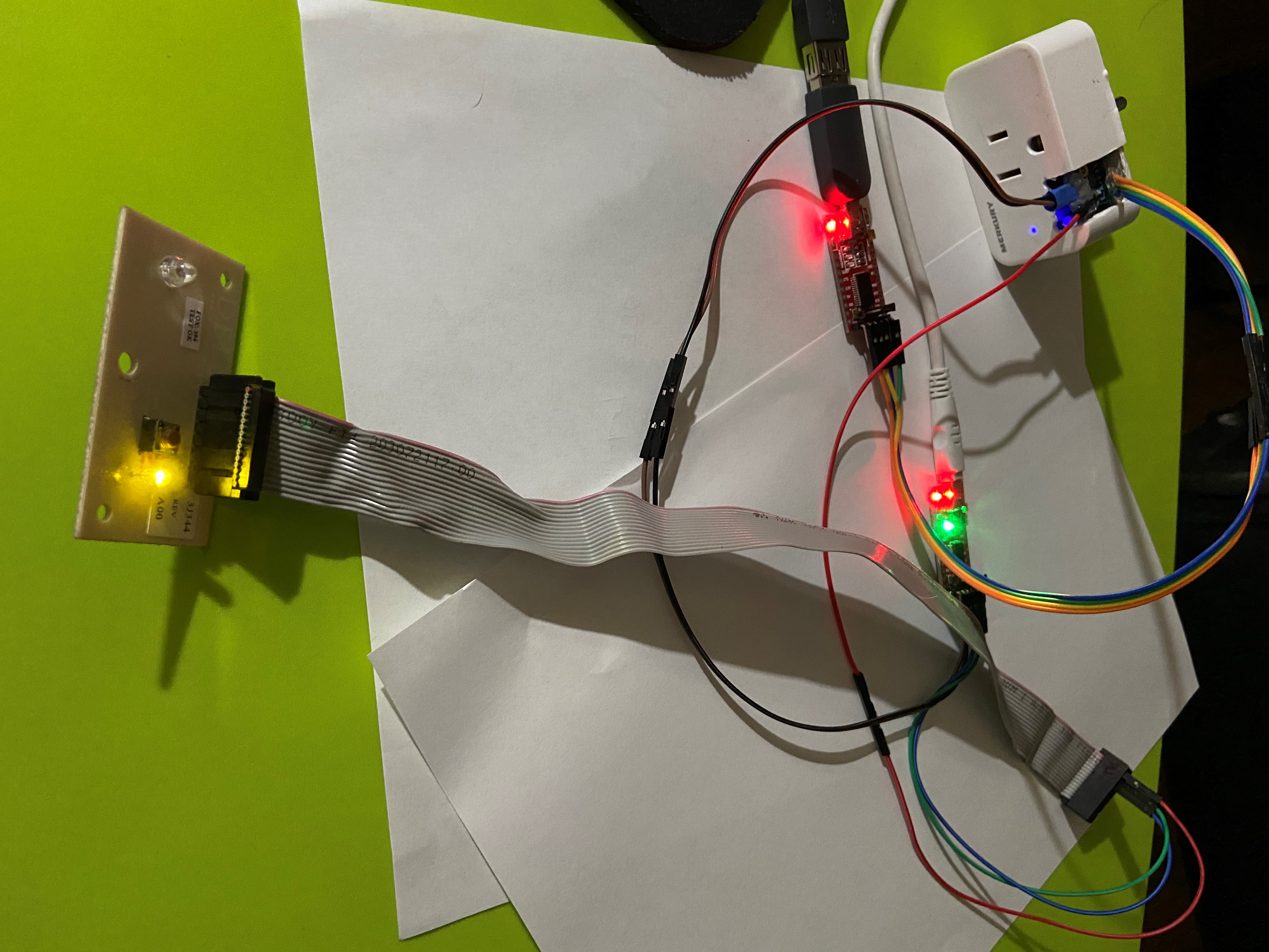 |
Device Log Setup - Listening in
Time to test the connections. First, I connected the FTDI that is connected to 2RX/2TX to the computer. For each of the serial adapters, a USB cable was used to connect instead of plugging directly into the USB port so everything wasn’t crammed into one place. Once connected, I checked to see what serial port it had been assigned.
For Windows10 open Device Manager with either right-click on the Start button or press the Windows key and x, then select Device Manager from the menu | Find the Ports (COM & LPT) section |
|---|---|
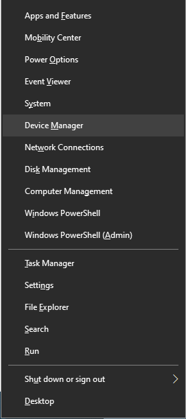 |  |
For Linux the command ls /dev/ttyUSB* from a terminal prompt will list the USB serial tty devices
user@host:~ $ ls /dev/ttyUSB*
/dev/ttyUSB0
To capture logging output I needed a terminal application to read the information being sent from the device. PuTTY works really well for this job with Windows.
A good terminal application for Linux would be the tried and true minicom.
Using PuTTY, I set the connection up as follows using COM3 from our device listing with a speed of 115200 baud and opened the connection.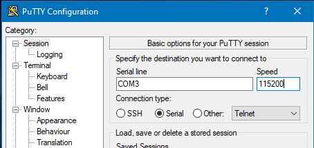
Because the plug will be powered from the FTDI device connected to the programming uart (1RX/1TX), I then connected the second adapter to the computer and was immediately greeted
with successful results. The log starts with the chip initializing and then goes through the bootloader and finally the application loads and searching for connection.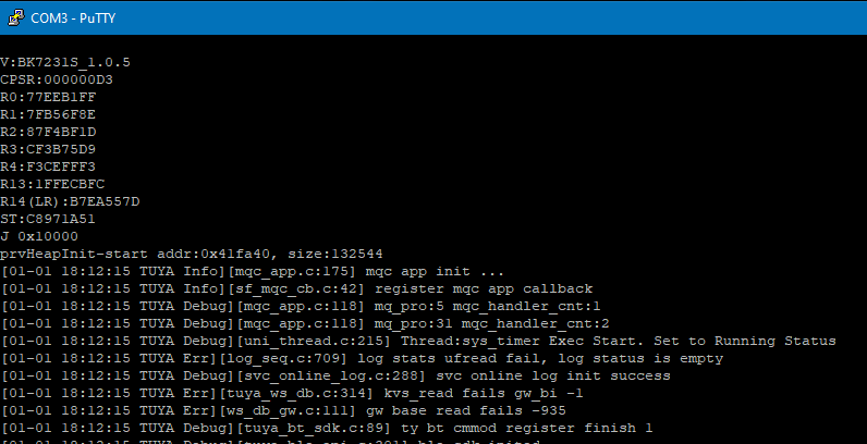
Firmware Dump Setup - A look inside
Prerequisites:
- Git Bash (actually optional, but what I used for my terminal)
- Python 3
This is the part where it really starts to get interesting. Once logging was established, it was time to take the programming uart (1RX/1TX) adapter for a spin.
While it is probably possible to do this section with Powershell, I have Git Bash which makes using a text console from Windows much more pleasant.
There is a Beken ‘official’ flashing application that was located for doing this part, but I found it to be completely useless because all it did was fail to connect. Instead I chose to use this fork of hid_download_py for the flash reading/writing. This will require an installation of Python 3 to run.
git clone https://github.com/OpenBekenIOT/hid_download_py.git
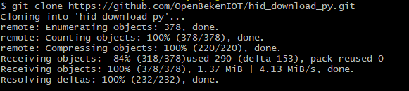
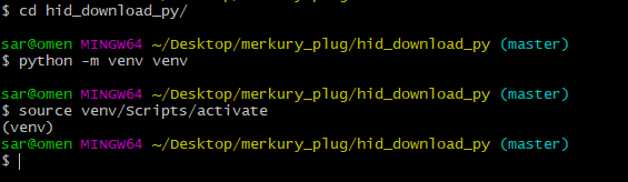
I initialized a python virtual environment to hold any additional modules that would be needed for the scripts to run and activated the environment. Using a virtual environment allows me to recover easily if an incorrect or incompatible python module gets installed. I can simply delete the venv directory and recreate the environment without any consequence to the system Python installation.
python -m venv venv
source venv/Scripts/activate
The uartprogram script requires a a few modules that I don’t yet have setup in my virtual environment, so I received a few errors when attempting to run it.
The Python pip command is used to install the missing modules:
pip install pyserial
pip install tqdm
I was then able to run python ./uartprogram --help to get the options.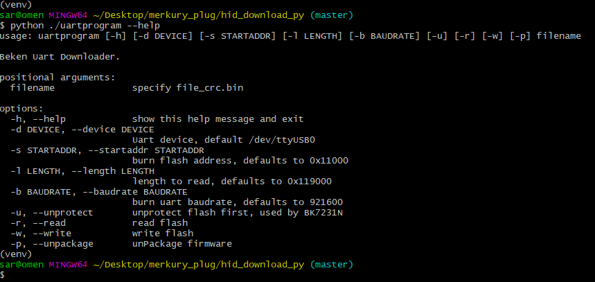
uartprogram program usage
Before attempting to write any firmware to the chipset, I needed to test if I could read from the chipset properly. I see from the usage that I need to use the
-d, -b, and -r options to specify the device, speed, and output file.
For the device to be in program mode I need to bring the CEN to ground for a moment while uartprogram is Getting Bus..., resetting the device. This is the reason I wired the reset
switch to the CEN, but I could get the same result by touching the CEN contact to GND or a quick disconnect/reconnect of GND.
I started the application to read with the following command, and as soon as it said Getting Bus...
I briefly grounded the CEN with the reset button and released. It took a few repeated tries to get the timing correct, just pressing and releasing the button every second or so,
but it eventually took and started reading.
python ./uartprogram -d COM6 -b 115200 -r ./firmware.bin
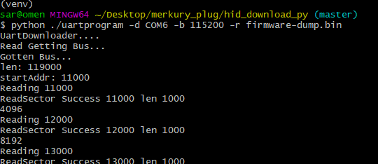
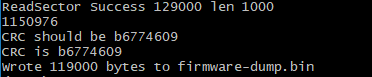
By default this script starts at address 0x11000, so this is only the application part of flash not including the bootloader. I was also able to copy the entire flash including
bootloader by specifying -s 0x000000 in the command to read. In the end for this project I didn’t need the bootloader, but I did break something on a later project and it came
in very handy to rescue a bricked device.
I now have logging and flash reading! Now on to the final goal, writing.
Preparing a Development Environment
Prerequisites:
- Microsoft Visual Studio Code
- PlatformIO extension for VSCode
Before I’m able to flash new firmware, I have to have firmware to flash. I have a few options available depending on my intentions for the device.
- Tuya SDK for this device is available, meaning I could modify the software for the plug and also still be able to use the mobile app.
- OpenBeken, the Tasmota/Esphome replacement based off of the Tuya SDK but also allowing for the untethering of the device from the Tuya Cloud.
- LibreTuya which creates an Arduino-compatible build environment for Tuya modules using PlatformIO.
Because I intend to use this device as an Arduino-like device and not to integrate into home automation, I chose to experiment further with VSCode/PlatformIO/LibreTuya.
Within VSCode, I installed PlatformIO according to the installation. I then opened a new terminal within VSCode,
and installed the LibreTuya platform into PlatformIO with the command:
platformio platform install https://github.com/kuba2k2/libretuya
Everything was now prepared to write my test application and flash the device.
The Final Boss - Flashing
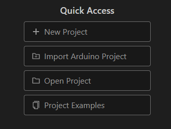
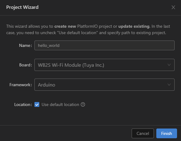
At this point I was ready to write a simple application to put all of this work to use. I created a New Project within PlatformIO specifying the WB2S board and
using the Arduino framework.
| PlatformIO Menu | Creating a New Project |
|---|---|
 |  |
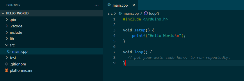
This created a basic Arduino project with setup() and loop() functions. The Serial.println() Arduino function is available, but so is printf(). I wrote a simple ‘Hello World’
output to show the firmware is loading properly after flashing.
I then ran the build from the PlatformIO Build button in the bottom left of the IDE to test compile the project into the firmware image.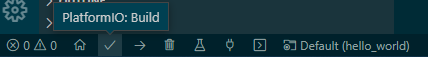
In order to upload the image I needed to modify the platformi.ini to specify which COM port I intended to use for upload. Without specifying this, the
program that LibreTuya and PlatformIO use to flash the chip will try to connect to COM3 which is currently connected as the logging adapter. A return to
Device Manager tells me that the programming adapter is found on COM6.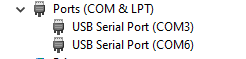
In Linux, more than likely the port needed would be whatever the logging TTY is +1 such as /dev/ttyUSB0 for logging and /dev/ttyUSB1 for programming.
This can be checked again with:
ls /dev/ttyUSB*
After adding upload_port = COM6 to the platformio.ini I was ready to try uploading ‘Hello World’.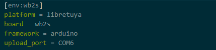
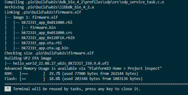
Using the PlatformIO Upload button this time, the project needed to recompile because of my addition to the platformio.ini and started to upload.
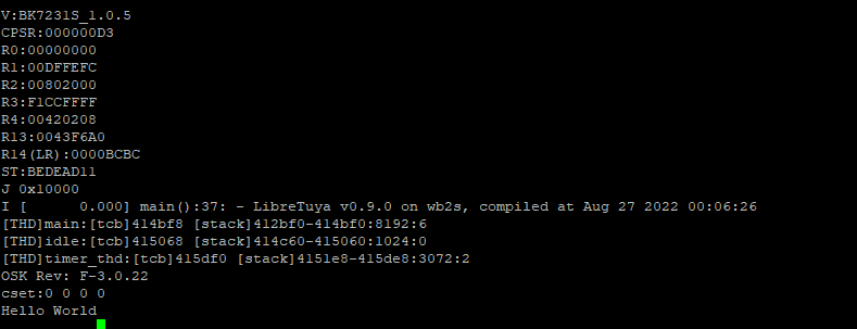
It is during this time that I start slowly and repeatedly pressing the reset button while watching the log in PuTTY until the flash starts. There is
now message specifying that it is flashing, but when it pauses printing text at the ST: line that is the sign. If it makes it to the J line or beyond,
the flash likely failed and will need to be retried. Once the flash is complete, the device should restart automatically and boot to Hello World.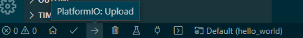
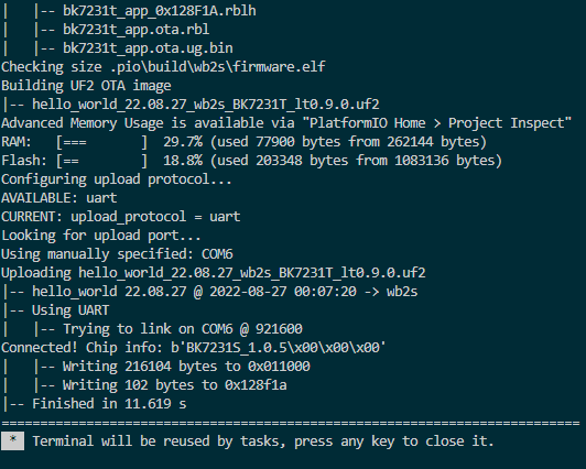
The PuTTY connection shows me the flash was successful and the new application runs with Hello World being printed.